Google server unreachable

Today I got my Honor 8 smartphone and while I set up things, I failed to login to my google account.

I got a message told me the google server was unreachable.

When I googled (like I always do), I found this article:

Honor 8 Google Server Unreachable (German)

I followed one instruction, told me to install the app:

  1. Search in google for “Aptoide apk” and install the app from their website
    (You have to trust their app)
  2. Start the app Aptoide and search for “Google Play Store”
  3. Update the Google Play Store App
  4. Now I can add my google account without getting this annoying message

Good luck.

(You can remove the Aptoide App after this)

How to update your Raspbian

  1. Connect via SSH to your Raspbian (How to set up a SSH remote connection to Raspbian and connect to it with PUTTY)
  2. write:

    sudo apt-get update

    and press ENTER
    update_1

  3. If it asks to continue, press Y and enter
  4. If the task is finished enter:

    sudo apt-get upgrade

  5. If it asks to continue, press Y and enter
    update_2

After finish, reboot and maybe repeat step 1-3

How to set up a SSH remote connection to Raspbian and connect to it with PUTTY

I will show you, how to activate the ssh remote console and connect it trough putty.

This tutorial based on everydaylinuxuser.

SSH stands for “Secure Shell” and describes a way to connect to a remote system in a secure way. With PUTTY we have a remote command line tool which can connect trough SSH to Raspbian.

We will do the following steps:

  1. First download and install PUTTY on your local machine (not the PI).
  2. Activate SSH Console inside of Raspbian
  3. Connect to Raspbian trough Putty

1. After downloading PUTTY you can start it and leave it

2. To activate the SSH Console, connect the PI to a HDMI Monitor and plug in a keyboard and mouse

piconfigmenu

  • Click on Menu -> Preferences -> Raspberry Pi Configuration (see image above)
  • In the new window click on Interfaces
  • At SSH click on Enabled
  • Click OK
  • Maybe you have to restart the pi

Hint: At the Raspberry Pi Configuration you can change a lot of internal settings, like the password etc.

The default username for Raspbian is: pi
The default password for Raspbian is: raspberry

putty_1

3. Inside of PUTTY enter raspberrypi as hostname and click on Open (see image above)

  • Maybe you get a warning, confirm with yes (see image below)

putty_2

  • If you did everything OK, you have to enter the username (pi) and the password (raspberry) and confirm it always with enter
  • Now you should be logged into Raspbian over SSH (see image below)

putty_3

Good you’re done

How to set up a Raspberry PI with Raspbian Jessie

This guide is based on the information given at raspberrypi.org.

First download the full image of raspbian jessie latest raspbian.

At this time it is the 2017-04-10-raspbian-jessie.zip.

Extract the .img file.

If you use windows, you can download the Win32 Disk Imager.

After installed and started the Win32 Disk Imager you see the following screen:


win32diskimager

Select the correct Image file and the Drive (e.g. F:\) and press “Write”.

win32diskimager_2

After process is completed, you can insert the sd card into your Pi and start the system.

Using Pi4J with Netbeans Remote Debugging

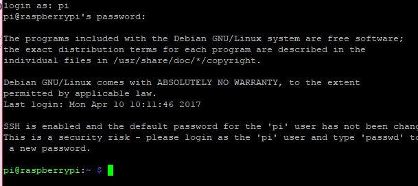
Since I started with my PI, I have to go trough a lot of reading.

Best IDE for programming JAVA with my Raspberry PI 3 was NetBeans, because it supports remote debugging (an awesome feature to program from my windows computer and deploy and run it at my PI).

Good article found here: Using Oracle Java SE Embedded with Raspberry PI

After installing and configuring my NetBeans, I started with a project.

On this site: Pi4J I found a good API to programm with the GPIO of the Raspberry PI.

I added the Pi4J Library to my System and then followed the instruction on this great video: Let’s Get Physical I/O Programming with Java on the Raspberry PI

Please keep in mind the GPIO Mapping to Pi4J is like this:

pi4j_pins

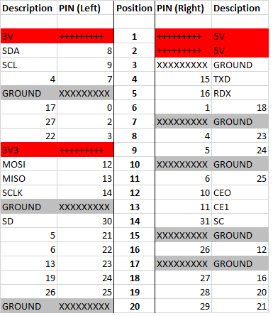
(Hard time to find out, would be faster if I had read Pi4J Website at PI Model 3B rev 1, but well it was some learning)

To find out, I wrote a program to input PIN Number to activate power or deactivate power on specific GPIO:

private static GpioPinDigitalOutput[] gpioPins;

private static long startTime = System.currentTimeMillis();

public static void main(String[] args) {

if(gpioPins == null)
{
GpioController gpio = GpioFactory.getInstance();
gpioPins = new GpioPinDigitalOutput[40];
gpioPins[0] = gpio.provisionDigitalOutputPin(RaspiPin.GPIO_00, “MyLED0”, PinState.LOW);
gpioPins[1] = gpio.provisionDigitalOutputPin(RaspiPin.GPIO_01, “MyLED1”, PinState.LOW);
gpioPins[2] = gpio.provisionDigitalOutputPin(RaspiPin.GPIO_02, “MyLED2”, PinState.LOW);
gpioPins[3] = gpio.provisionDigitalOutputPin(RaspiPin.GPIO_03, “MyLED3”, PinState.LOW);
gpioPins[4] = gpio.provisionDigitalOutputPin(RaspiPin.GPIO_04, “MyLED4”, PinState.LOW);
gpioPins[5] = gpio.provisionDigitalOutputPin(RaspiPin.GPIO_05, “MyLED5”, PinState.LOW);
gpioPins[6] = gpio.provisionDigitalOutputPin(RaspiPin.GPIO_06, “MyLED6”, PinState.LOW);
gpioPins[7] = gpio.provisionDigitalOutputPin(RaspiPin.GPIO_07, “MyLED7”, PinState.LOW);
gpioPins[8] = gpio.provisionDigitalOutputPin(RaspiPin.GPIO_08, “MyLED8”, PinState.LOW);
gpioPins[9] = gpio.provisionDigitalOutputPin(RaspiPin.GPIO_09, “MyLED9”, PinState.LOW);
gpioPins[10] = gpio.provisionDigitalOutputPin(RaspiPin.GPIO_10, “MyLED10”, PinState.LOW);
gpioPins[11] = gpio.provisionDigitalOutputPin(RaspiPin.GPIO_11, “MyLED11”, PinState.LOW);
gpioPins[12] = gpio.provisionDigitalOutputPin(RaspiPin.GPIO_12, “MyLED12”, PinState.LOW);
gpioPins[13] = gpio.provisionDigitalOutputPin(RaspiPin.GPIO_13, “MyLED13”, PinState.LOW);
gpioPins[14] = gpio.provisionDigitalOutputPin(RaspiPin.GPIO_14, “MyLED14”, PinState.LOW);
gpioPins[15] = gpio.provisionDigitalOutputPin(RaspiPin.GPIO_15, “MyLED15”, PinState.LOW);
gpioPins[16] = gpio.provisionDigitalOutputPin(RaspiPin.GPIO_16, “MyLED16”, PinState.LOW);
gpioPins[17] = gpio.provisionDigitalOutputPin(RaspiPin.GPIO_17, “MyLED17”, PinState.LOW);
gpioPins[18] = gpio.provisionDigitalOutputPin(RaspiPin.GPIO_18, “MyLED18”, PinState.LOW);
gpioPins[19] = gpio.provisionDigitalOutputPin(RaspiPin.GPIO_19, “MyLED19”, PinState.LOW);
gpioPins[20] = gpio.provisionDigitalOutputPin(RaspiPin.GPIO_20, “MyLED20”, PinState.LOW);
gpioPins[21] = gpio.provisionDigitalOutputPin(RaspiPin.GPIO_21, “MyLED21”, PinState.LOW);
gpioPins[22] = gpio.provisionDigitalOutputPin(RaspiPin.GPIO_22, “MyLED22”, PinState.LOW);
gpioPins[23] = gpio.provisionDigitalOutputPin(RaspiPin.GPIO_23, “MyLED23”, PinState.LOW);
gpioPins[24] = gpio.provisionDigitalOutputPin(RaspiPin.GPIO_24, “MyLED24”, PinState.LOW);
gpioPins[25] = gpio.provisionDigitalOutputPin(RaspiPin.GPIO_25, “MyLED25”, PinState.LOW);
gpioPins[26] = gpio.provisionDigitalOutputPin(RaspiPin.GPIO_26, “MyLED26”, PinState.LOW);
gpioPins[27] = gpio.provisionDigitalOutputPin(RaspiPin.GPIO_27, “MyLED27”, PinState.LOW);
gpioPins[28] = gpio.provisionDigitalOutputPin(RaspiPin.GPIO_28, “MyLED28”, PinState.LOW);
gpioPins[29] = gpio.provisionDigitalOutputPin(RaspiPin.GPIO_29, “MyLED29”, PinState.LOW);
gpioPins[30] = gpio.provisionDigitalOutputPin(RaspiPin.GPIO_30, “MyLED30”, PinState.LOW);
gpioPins[31] = gpio.provisionDigitalOutputPin(RaspiPin.GPIO_31, “MyLED31”, PinState.LOW);
}

do{

try {

System.out.println(“Please enter a PIN to toggle (0-31):”);
BufferedReader buffer=new BufferedReader(new InputStreamReader(System.in));
String line=buffer.readLine();
int number = Integer.parseInt(line);
if(number < 0 || number > 31)

continue;

gpioPins[number].toggle();
System.out.println(“PIN number ” + number + ” turned ” + (gpioPins[number].getState().isHigh() ? “ON” : “OFF”));

} catch (IOException ex) {

Logger.getLogger(HelloWorld.class.getName()).log(Level.SEVERE, null, ex);

}

}
while(System.currentTimeMillis() – startTime < (1000*60*10));

System.out.println(“Program ends…”);

Now I am trying to get a button ready, like supposed in the video.

Using the Raspberry Pi 3 with a 5200mA powerbank

Intentionally a friend of mine asked the question if a normal mobile phone powerbank can power the Raspberry Pi 3 and I had some laying around, so I tested it.

IMG_20170610_153936

I used some powerbank with 5200mA (see Image above).

I put the Raspberry Pi on the 2,1A power supply and it ran for 4 hours and 48 minutes.

Plugged devices:

  • USB 3.0 Segeate 1TB HDD
  • USB Logitech WebCam
  • Logitech Universal Receiver
  • HDMI (1920×1080)


How to create a (windows) share with Raspbian

Here I show how to create a (windows) share on a raspbian running raspberry pi

It took me some google search to found this good article:

Share Linux folder to Windows

When I tried out I missed some steps.

First I connected to my Pi with PUTTY

After that I created a new User who will be granted for accessing the share

sudo adduser NAME –no-create-home –force-badname –disabled-login

Where NAME has to be replaced with any name you prefer. (I used Patrizio 😉

After successfully created the User, I followed the instruction on the article above.

sudo apt-get install samba

With this command I installed the samba server to share to windows.

After successfully installed the samba server, I set the samba user with (replace NAME with you choosen one)

sudo smbpasswd -a NAME

You can choose the same password like adding the user before.

I made a Folder inside the home folder

mkdir share

and set the permissions with

chmod -R 777 Share

After that, I had to change the samba server’s config file with

sudo nano /etc/samba/smb.conf

Added the following lines at the end of the file

[Share]
path = /home/Share
avaible = yes
valid users = NAME       #NAME of the created user
read only = no
browsable = yes
public = yes
writable = yes

Obviously you can change the settings to fulfill your needs.

Last but not least I restarted the samba server with

sudo service smbd restart

When I accessed the share with my windows machine, I got this result:

raspberrypi_share

Now I can write files to the Raspberry Pi from my Windows machine 🙂